Constraints
For my project, I ordered two modules of a flip dot matrix. As the size of the matrix is a formal constraint, this is what I had to begin with.

Next to the size, of course the dots of the matrix is a limitation. Not necessarily what I can display, rather how I have to display it. For the modules I found, this would mean a matrix of two times 5 ✕ 7, consequently a final matrix of 10 ✕ 7. I created a quick prototype in a P5 sketch to be able to test out different variations quickly. I did not want to focus on this now, so at the moment it only creates random patterns when clicking on it:
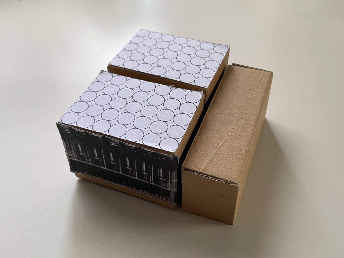
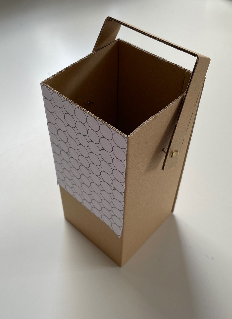
Cardboard Mockups
I wanted to understand the different shapes and sizes of the object. I first built volume models of the flip dot components with the sizes mentioned before. I wanted to get a feeling about the arrangement and size I would need in general.
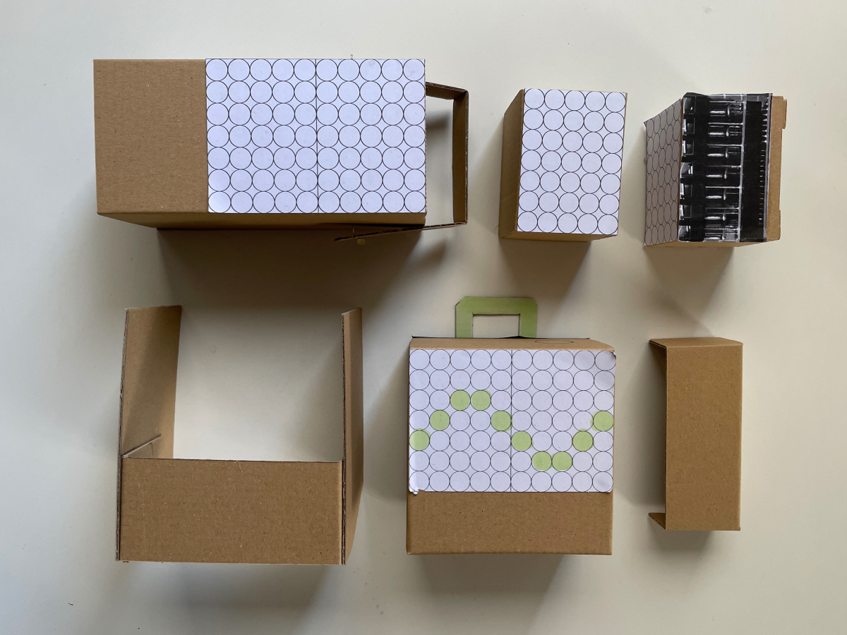
I wanted to understand what would be the best shape to allow me putting it on my desk and reading it, but also to hang it on the wall, as described in my text. Yet each module has a matrix of 5 ✕ 7 flip dots, but how I arrange them is still open. Thinking about the other components I would need to include in the prototype, I intended some space to include in it as well.
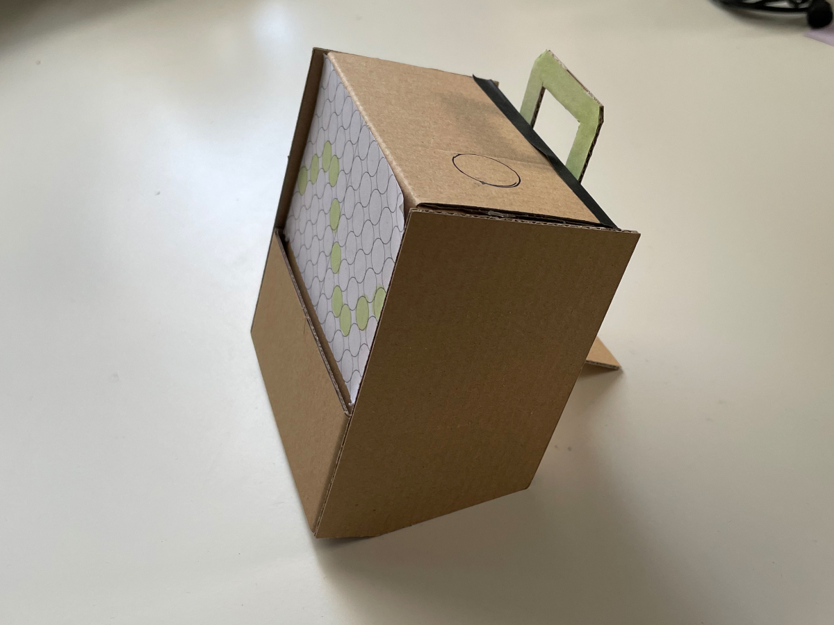
My general intention is to emphasize on the flip dots, the central element of the communication piece. I like the general open aesthetic of the dots, the mechanical elements making the flip visible. Hence, they should not be covered by a glass. This fascination about the dots also got me thinking if the case therefore should also not flush with the top edge of the flip dots but rather with the edge of the PCB of the components.
As the matrixes are fairly big in general, I also thought about all the other components that I would need for the object to be working (see below ↓) to understand how much space I need to consider. This has been the foundation of my further experiments. Also thinking about how to make it less generic and including smaller features to make it more useful.
Interface Mockups
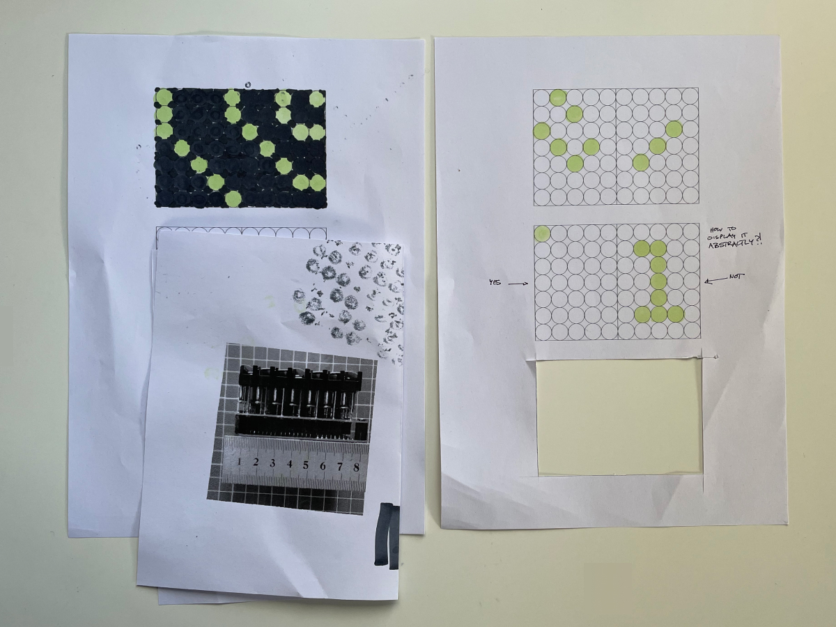
As the matrix is the most relevant piece of the whole object, I thought about how to represent messages on it. I printed a sheet with empty matrixes to test out quickly different interface ideas, some more abstract, some more specific.
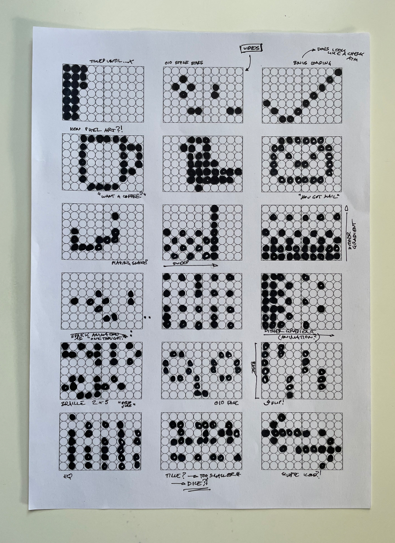
Generally I like the ‘more abstract’ approach better as it inherits more space for interpretation, thus giving a more human connotation to the message. But I also had a look at 1 bit pixel icons as the have the same issue when it comes to resolution. I could imagine that this would also inherit a nice way of displaying a message, depending on the message of course.

Also inspired by this animation ↑ (seen on oio.studio), I could imagine that instead of just images small animations could display messages quite well. Especially considering the ‘click’ sound the flip dots make when changing color, the sound of the matrix together with the animations could play together nicely.
Software Architecture
For the prototype, I want to build up on the LittleBigPrinter architecture that I have created already, to make this part easier and be able to focus on the interaction rather than the technicalities. Hence I have a setup as shown below ↓
- Website — A website to send out messages and create a virtual prototype to understand the connection. I want to use Next.js, as I am more familiar with the framework and it enables me to easily build the communication.
- Database — I need some sort of connection point between the elements, so I am thinking of a Firebase database, as it would enable me to do realtime communication between the components.
- Hardware Object — The actual object. It needs to have a microcontroller that is able to connect to the internet to fetch updates of the database, something like a Raspberry Pi or an Arduino with an esp8266. This is the actual object containing the flip dot elements.
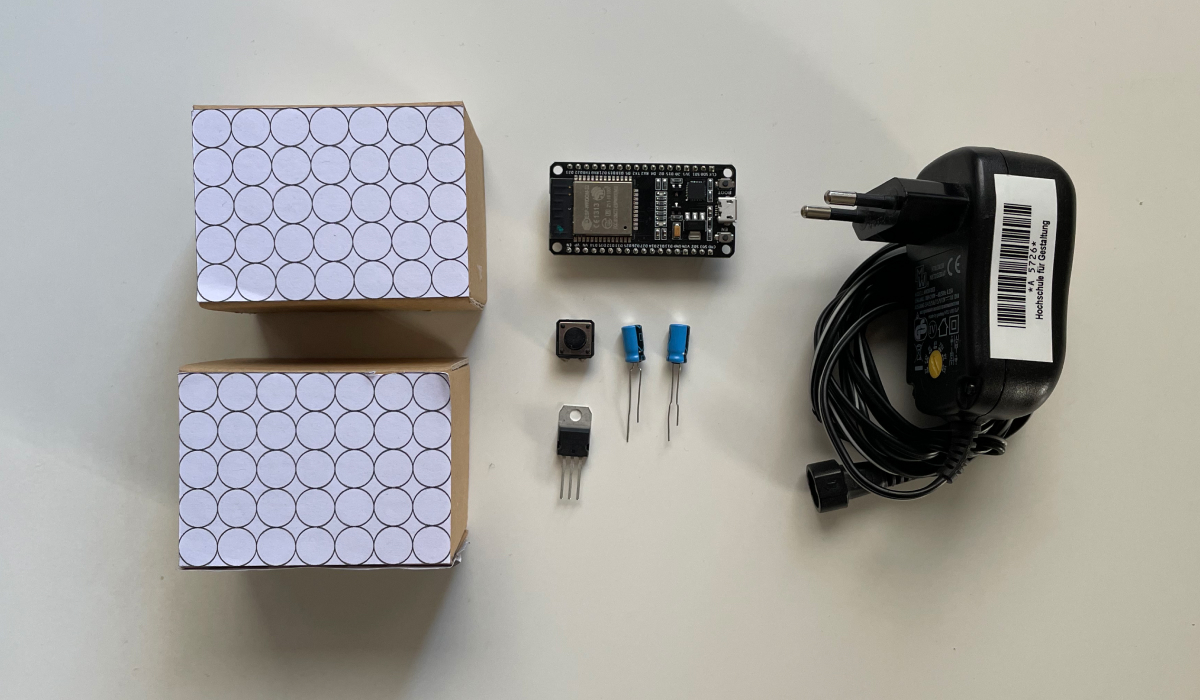
Elements
I also checked which components I would probably need to create a functional prototype. I generally need a brain of some sort to control the hardware. Initially, I was thinking about using an Raspberry Pi, but it probably is a little overpowered. I also found a library to connect an ESP32 with Firebase, which seems like a more lightweight and smarter solution, so I am currently planning with a setup similar as the following:
- ESP32 — the microcontroller that is able to connect to the WiFi and otherwise behaves like an Arduino
- voltage regulator — transforming the required 12V for the flip dot matrix to 5V that the ESP32 needs to run
- 2 ✕ 10µF Capacitors — to ensure the security of the converted voltage
- button — to trigger actions as described in the concept
- 10kΩ resistor — for the button to work properly
- 12V power adapter — to give the box power
I am facing some issues when trying to program the ESP due to the new macOS Big Sur update. Currently, I am following this issue to solve the issue.
How to continue
For the next steps I want to (1) build the object to have the platform running, (2) create a base website layer to easily test out the communication methods, and (3) create assets, symbols, and animations to test different ways of displaying messages. I want to build upon the P5 sketch as seen above as I think this might be the best way to easily display the multiple variations of the matrix display.